
Jul 25
Arduino IDE on ESP8266 (NodeMCU dev board) Notes - ESP8266
Using the Arduino IDE and the Arduino eco-system to build firmwares for an ESP-12E (ESP8266 dev board, usually called NodeMCU) is actually quite easy.
Here are some pointers I noted along the way:
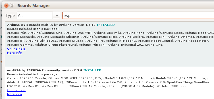
- Adafruit has a nice step by step instruction of getting the Arduino IDE up and running with an ESP8266 board. You're basically done after "installing" your ESP board via the "Boards Manager" (Menu > Tools) and setting baud rate and (USB) port.
- On Linux (Ubuntu), Arduino IDE will not be able to upload sketches (or communicate with the board at all) if you don't change permissions on /dev/ttyUSB0 appropriately. Same as with the NodeMCU ESPlorer IDE, btw... For example, do this:
you@your_pc:~$ ls -al /dev/tty* | grep USB
sudo chown you:dialout /dev/ttyUSB0(...where you replace "you" with your username). With ESPlorer I simply ran it as root, out of lazyness, but Arduino IDE will create dotfile config data, and that will end up in the root account. Note to myself: Let's just end this habit of running something as superuser with the switch to Arduino IDE).
Update: The official Arduino Docs suggest adding yourself to the dialout or uucp groups which is the right way to do it , after all.
- Read the ESP8266 Arduino Reference, cover to cover (it's not that much).
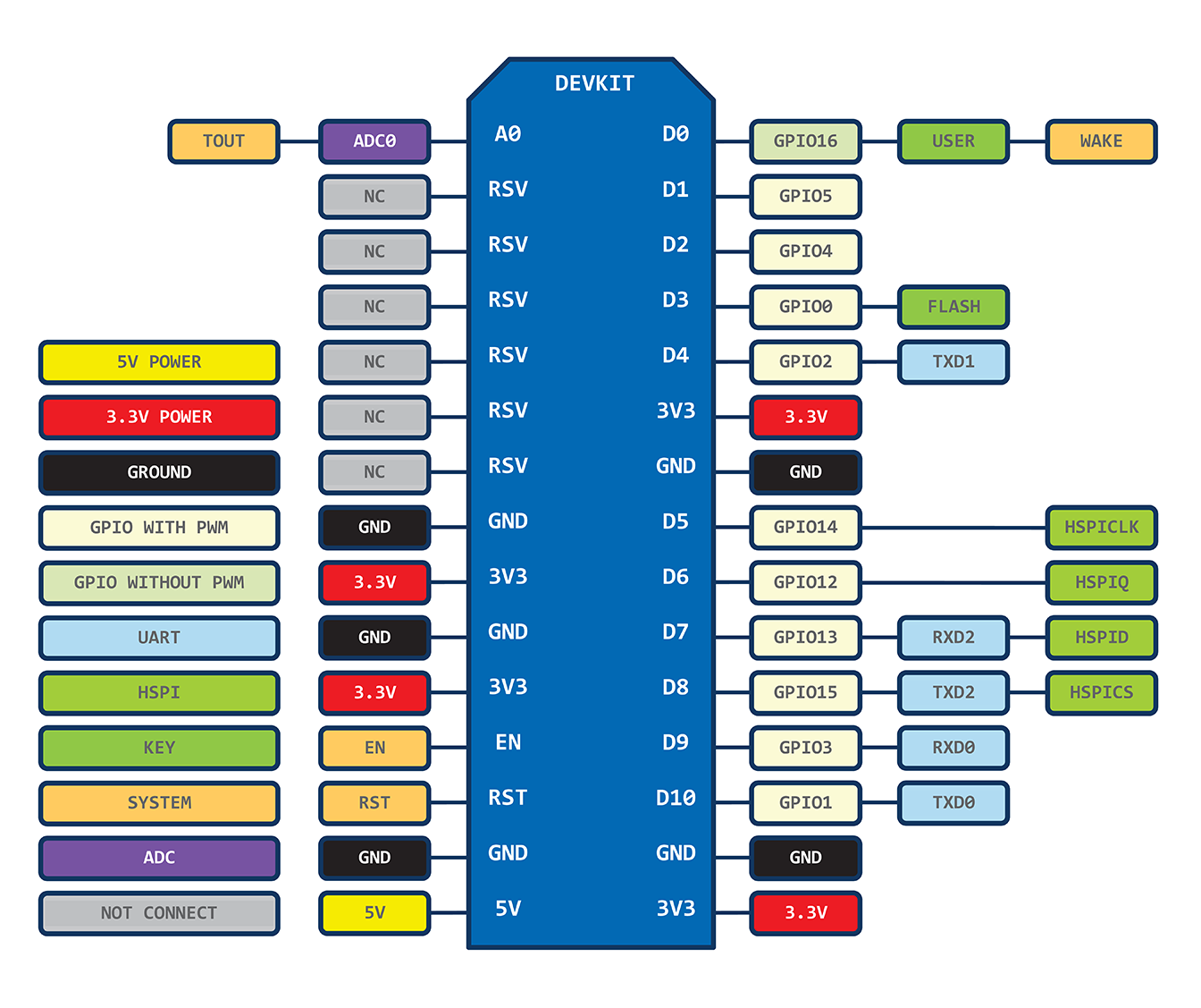
- The Pin labelling on the ESP8266 is a bit of a challenge. As noted earlier, sometimes even the printed labels are wrong. Then there is this confusion about "internal" ESP GPIO pins, and the "canonical" labelling as pins D1 - D16. I have found this pinout schematic to be very handy - bookmark it! The Reference Docs has another, more confusing one.
As a rule of thumb, when you write a sketch in Arduino IDE, either use the convenience constants recent Arduino IDE versions should provide (just write "D1" in your code and forget about internal GPIO numbering), or
use the schematic, look-up on which pin your connection is, trace out the corresponding GPIO number and use that in your code. For example the schematic shows that a connection on NodeMCU pin D1 means it's GPIO pin 5, so use value 5 in your sketch. - Observation: While replacing what the ESP is supposed to do, the program, is really easy and quick with the LUA runtime of NodeMCU, for example via "upload + dofile()", it's a "real" compilation and full flash flashing cycle each time with Arduino IDE - slowing things really down. But only out of the box!! Right after having the IDE up and running, you should switch Tools > Upload Speed to a baud rate above 115200, like 460800 or even 921600. Try what works for you. Also, when code is actually on the micro-controller, things feel snappier, and especially with driving an OLED i2c communication and resulting display refresh rates seem to have lost a lot of lag. While my test combination of a 128x64 OLED was limited to max 4fps via i2c on NodeMCU firmware, I'm going 20fps easily via Arduino firmware.
- Note: in contrary to NodeMCU LUA, where putting the CPU into a busy loop with delay() is one of the bigger sins of coding, in Arduino firmware land it's actually a good thing! You are encourage to use it, if needed and if you have too few "delays" have to put them in here and there for good measure. (read yourself) While a delay in NodeMCU+LUA will keep the WiFi stack from doing its thing, in Arduino+Arduino-sketch-code land a delay will allow the CPU to do WiFi housekeeping.
For completeness: If you're interested in the source code for the embedded video above - here it is. It's simply a demo script from elsewhere, adapted to my pin-out wiring.
// https://github.com/squix78/esp8266-oled-ssd1306/blob/master/examples/SSD1306DrawingDemo/SSD1306DrawingDemo.ino


  // #include <Wire.h>  // Only needed for Arduino 1.6.5 and earlier
  // #include "SSD1306.h" // alias for `#include "SSD1306Wire.h"`

  // Initialize the OLED display using Wire library
  // SSD1306  display(0x3c, D3, D5);
  // SSD1306  display(0x3c, 5, 4);

  // or #include "SH1106.h" alis for `#include "SH1106Wire.h"`
  // For a connection via I2C using brzo_i2c (must be installed) include
  #include <brzo_i2c.h> // Only needed for Arduino 1.6.5 and earlier
  #include "SSD1306Brzo.h"

  // Initialize the OLED display using brzo_i2c
  // D3 -> SDA // NodeMCU D1 = GPIO5
  // D5 -> SCL // NodeMCU D2 = GPIO4
  // SSD1306Brzo display(0x3c, D3, D5);
  SSD1306Brzo display(0x3c, 5, 4);


// Adapted from Adafruit_SSD1306
void drawLines() {
  for (int16_t i=0; i<DISPLAY_WIDTH; i+=4) {
    display.drawLine(0, 0, i, DISPLAY_HEIGHT-1);
    display.display();
    delay(10);
  }
  for (int16_t i=0; i<DISPLAY_HEIGHT; i+=4) {
    display.drawLine(0, 0, DISPLAY_WIDTH-1, i);
    display.display();
    delay(10);
  }
  delay(250);

  display.clear();
  for (int16_t i=0; i<DISPLAY_WIDTH; i+=4) {
    display.drawLine(0, DISPLAY_HEIGHT-1, i, 0);
    display.display();
    delay(10);
  }
  for (int16_t i=DISPLAY_HEIGHT-1; i>=0; i-=4) {
    display.drawLine(0, DISPLAY_HEIGHT-1, DISPLAY_WIDTH-1, i);
    display.display();
    delay(10);
  }
  delay(250);

  display.clear();
  for (int16_t i=DISPLAY_WIDTH-1; i>=0; i-=4) {
    display.drawLine(DISPLAY_WIDTH-1, DISPLAY_HEIGHT-1, i, 0);
    display.display();
    delay(10);
  }
  for (int16_t i=DISPLAY_HEIGHT-1; i>=0; i-=4) {
    display.drawLine(DISPLAY_WIDTH-1, DISPLAY_HEIGHT-1, 0, i);
    display.display();
    delay(10);
  }
  delay(250);
  display.clear();
  for (int16_t i=0; i<DISPLAY_HEIGHT; i+=4) {
    display.drawLine(DISPLAY_WIDTH-1, 0, 0, i);
    display.display();
    delay(10);
  }
  for (int16_t i=0; i<DISPLAY_WIDTH; i+=4) {
    display.drawLine(DISPLAY_WIDTH-1, 0, i, DISPLAY_HEIGHT-1);
    display.display();
    delay(10);
  }
  delay(250);
}

// Adapted from Adafruit_SSD1306
void drawRect(void) {
  for (int16_t i=0; i<DISPLAY_HEIGHT/2; i+=2) {
    display.drawRect(i, i, DISPLAY_WIDTH-2*i, DISPLAY_HEIGHT-2*i);
    display.display();
    delay(10);
  }
}

// Adapted from Adafruit_SSD1306
void fillRect(void) {
  uint8_t color = 1;
  for (int16_t i=0; i<DISPLAY_HEIGHT/2; i+=3) {
    display.setColor((color % 2 == 0) ? BLACK : WHITE); // alternate colors
    display.fillRect(i, i, DISPLAY_WIDTH - i*2, DISPLAY_HEIGHT - i*2);
    display.display();
    delay(10);
    color++;
  }
  // Reset back to WHITE
  display.setColor(WHITE);
}

// Adapted from Adafruit_SSD1306
void drawCircle(void) {
  for (int16_t i=0; i<DISPLAY_HEIGHT; i+=2) {
    display.drawCircle(DISPLAY_WIDTH/2, DISPLAY_HEIGHT/2, i);
    display.display();
    delay(10);
  }
  delay(1000);
  display.clear();

  // This will draw the part of the circel in quadrant 1
  // Quadrants are numberd like this:
  //   0010 | 0001
  //  ------|-----
  //   0100 | 1000
  //
  display.drawCircleQuads(DISPLAY_WIDTH/2, DISPLAY_HEIGHT/2, DISPLAY_HEIGHT/4, 0b00000001);
  display.display();
  delay(200);
  display.drawCircleQuads(DISPLAY_WIDTH/2, DISPLAY_HEIGHT/2, DISPLAY_HEIGHT/4, 0b00000011);
  display.display();
  delay(200);
  display.drawCircleQuads(DISPLAY_WIDTH/2, DISPLAY_HEIGHT/2, DISPLAY_HEIGHT/4, 0b00000111);
  display.display();
  delay(200);
  display.drawCircleQuads(DISPLAY_WIDTH/2, DISPLAY_HEIGHT/2, DISPLAY_HEIGHT/4, 0b00001111);
  display.display();
}

void printBuffer(void) {
  // Initialize the log buffer
  // allocate memory to store 8 lines of text and 30 chars per line.
  display.setLogBuffer(5, 30);

  // Some test data
  const char* test[] = {
      "Hello",
      "World" ,
      "----",
      "Show off",
      "how",
      "the log buffer",
      "is",
      "working.",
      "Even",
      "scrolling is",
      "working"
  };

  for (uint8_t i = 0; i < 11; i++) {
    display.clear();
    // Print to the screen
    display.println(test[i]);
    // Draw it to the internal screen buffer
    display.drawLogBuffer(0, 0);
    // Display it on the screen
    display.display();
    delay(500);
  }
}


void setup() {
  display.init();

  // display.flipScreenVertically();


}

void loop() {
  display.setContrast(255);

  spinCube();
  delay(1000);
  display.clear();

  drawLines();
  delay(1000);
  display.clear();

  drawRect();
  delay(1000);
  display.clear();

  fillRect();
  delay(1000);
  display.clear();

  drawCircle();
  delay(1000);
  display.clear();

  printBuffer();
  delay(1000);
  display.clear();
}
--
This post is part of a series of Mini Tutorials on the ESP8266:
Previous post: How to receive UDP data on NodeMCU + LUA + ESP8266
I'm tinkering here with a NodeMCU ESP8266 (ESP-12E) board.
I'm using the Arduino IDE.